
Nikon SDC - Mode of operation
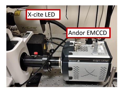
This microscope offers several capabilities, it has two light sources and one camera. In addition to the laser system, you can use the X-cite LED in widefield mode. The camera installed is an EMCCD iXon 888 with 13 µm pixels in a 1024 x 1024 format.
Microscope controls
To control the microscope stage, you will use the joystick. The central knob controls the X and Y directions, you can change the speed by twisting the top of it.
The knob on the side of the joystick can be used to lower or raise the objective and bring the sample into focus. You can also do this by using the two knobs on each side of the microscope itself. Note: On Nikon microscopes, when you turn your fingers UP the objective goes UP and vice versa.

This microscope has a Perfect Focus System that facilitates focus finding. Please refer to Using the Perfect Focus System (PFS) page to use it.
Overview of the Optical Configuration (OC) control panel
The OC Panel contains the different light source configurations (referred to as “Light Paths” and their corresponding preset parameters (listed as “General” but referred to as “Optical Configurations”). You most likely will use the Spinning Disk configuration to observe your sample using the lasers and camera, and possibly the Eyepiece – EPI configuration to find the sample in widefield mode with your eyes if needed. Just below Light Paths you can find the selection of channels (OCs). Select the OC that corresponds to your fluorophores. To help, you can find the list of OCs and their corresponding fluorophores on the wall behind the computer monitor.
-
The Ti Full Pad
The Ti Full Pad allows you to choose the objective you need, orient the light path to the detector (here it is on the right port) and adjust the focus with the software. Note: If you adjust the Z height in the software, the PFS will turn off.

-
Light Sources
The OC panel has the different light sources you may use. You can adjust the intensity of the diascopic transmitted light (DIA) for general widefield transmitted light or select the laser line you are using and change its intensity. Note: The laser must be turned on (illuminated) on the laser combiner for the control to occur.

-
Spinning Disk Mode
The Spinning Disk mode is the mode you will principally use on the Nikon Spinning Disk Confocal. Make sure you selected this configuration to be able to control the laser lines.

-
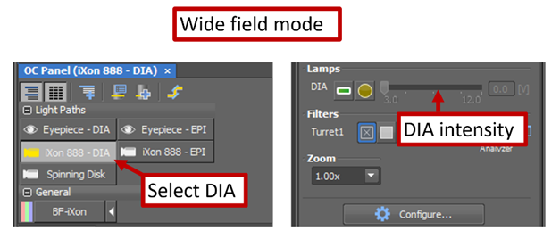
Widefield Mode
It is sometimes useful to use the widefield mode to find the sample and bring it into focus. Select iXon 888 – DIA as a configuration and then you can adjust the lamp intensity.
-
EMCCD Controls
The iXon 888 Pad contains the camera settings. You have the option to apply binning to the images. However, remember this will lower the image quality. The exposure can be adjusted here to have more signal from your sample or avoid saturation. The EMCCD can be used as a regular CCD if you leave the EM gain off. To benefit from the electron multiplying gain you need to set it to a specific value. Note: Do not exceed a gain value of 300 as there is a diminished benefit to the image quality as well as the linearity of the signal amplification is lost. The Camera Region of Interest (ROI) is defined to match the usable field of view of the camera.

Scan Acquisition
At this point in your training it was time to look at the sample and start an acquisition. We used a demo sample with the 20X objective, air immersion. If you are using the 100x oil immersion objective, start by dropping a drop of oil on the top of the objective, as described in this tutorial video.
Note: You cannot use an air objective after you have imaged your sample with an oil objective. This is because the oil can transfer from the sample to the objective, and can result in both diminished image quality as well as damage the objective itself. Please thoroughly clean your sample and the 100x objective prior to using the air objective.
Now that you have delicately placed your sample on the sample plate holder you need to:
-
Bring the sample into focus using the PFS:
A. Press the PFS button on the microscope base. You will hear several beeps and the light will start blinking, indicating that the microscope is searching for the focal plane.
B. Raise the objective slowly using the black knob on the side of the joystick until you hear a beep. The PFS button will be continuously lit when perfect focus is engaged correctly and the LED next to the FOCUS display will be lit. Be careful not to push the objective into your sample - this will damage the objective and lead to costly repairs.
C. Click “Live” in Nikon Elements to observe the sample
D. Autoscale your Look-Up Table (LUT)
E. Adjust the focus using either the external knobs or the controls in the software.
F. Adjust the Laser Power, Exposure Time, and/or EM Gain to refine your image quality.
-
Optimizing the image
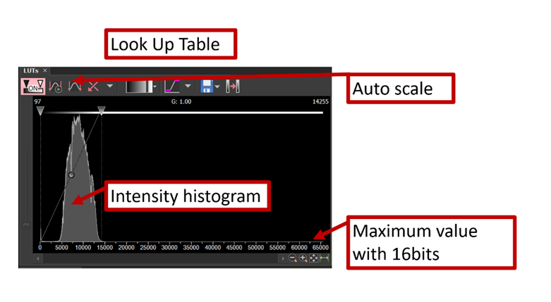
Depending on the camera you are using and how much signal your sample emits with the laser settings that you chose, your image may be very dim to start with, to the point that you don’t see anything. The first thing you should do is adjusting the Look Up Table.
To auto-adjust the lookup tables, clicking on the Auto Scale buttons above the image of interest.
 This button will adjust the lookup table for each frame (useful in live view mode)
 This button will adjust the lookup table for the current image
You can also set the range of the Look Up Table by dragging the lines on either side of the intensity histogram with the little triangular cursor on the top. If the intensity histogram reaches the end of the range that means your image is saturated and you need to reduce the laser power or the exposure time or both.
-
Adjusting the exposure and laser power
In the Camera Settings Pad you can adjust the exposure of your image. You can also choose to bin your image (i.e clumping the pixels together to make bigger pixels). With the EMCCD camera, binning will improve the sensitivity of the pixels but they are now twice as big so you will lose in image sharpness (resolution).
Now that you found the sample, brought it in focus and optimized its signal, you may want to select a specific cell and center it in the image. You can always do this using the joystick of course. But there is another useful way to perfectly center the cell you choose. If you right click on the image viewer where the cell is located you can find the option to center it and the stage will move accordingly.
Another useful feature of Nikon Elements is the option to save your field of view in the image format of your choice. This will be a view only image, it won’t allow you to process the different channels separately and such. But you may find this useful to show your colleagues or for later comparison with other data sets. To do so, click on the “x” letter on the keyboard and you will find the option to save in the format of your choice.
Image acquisition and saving
The Nikon Elements software offers many options for acquiring and saving your data. For SDC experiments you will typically want to acquire a z-stack and possibly for different channels at different wavelengths.
-
Acquiring a z-stack image for different channels
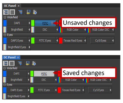
Before you start acquiring and saving data, you need to assign the settings you chose. When you open the software, each channel is set at its default settings. After finding your sample, you probably changed some settings so that the image looks as good as it can.
You should see a little “!” in the corresponding channel buttons. Click on the arrow next to it to assign the settings. When the “!” mark disappears your changes should be saved and you are ready to move on to the acquisitions.
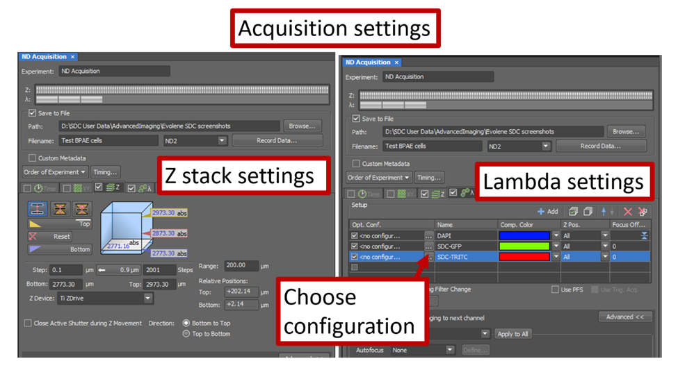
In the ND Acquisition Panel, check the box to “Save to File” and choose your destination and filename.
A. To acquire a time lapse image stack, you need to check the box that says Z and the box that says λ.
B. Then you can define your acquisition settings for Z: number of steps, start and end point, range, step size and order of acquisition.
C. Define the acquisition settings for the different wavelengths. You need to choose a configuration for each channel (those are pre-set in the software).
D. After you defined all the settings, click “Order of Experiment” to define in which order you want the scan to proceed.
E. When you are ready to image click “Run now”
While the scan is in progress you will see this window:

Finally, you can use the scanning wizard to tile several scan areas together. This option is found in the Addons menu. Select “Scanning wizard”. You can find options for the scan there, define the number of tiles and in which order the scan goes.

Look at your z-stack in Nikon Elements
-
Maximum Intensity Projection
Once the acquisition is complete you can look at its maximum intensity projection.

-
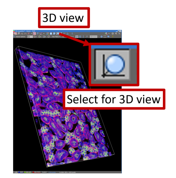
3D View of the sample
The 3D viewer allows you to look at the full z stack in all directions. It can be useful for nice renderings too!
No Comments