
Choosing the most appropriate camera for your experiment
Introduction
In this guide you will learn how to identify what kind of detector is appropriate for your experiment, how to understand the main specifications of the two types of cameras you will encounter the most in biological imaging and relate them to your needs.
Nowadays, both sCMOS (scientific Complementary Metal Oxide Semiconductor) and EMCCD (Electron Multiplying Charge Coupled Device) cameras can be used for biological imaging and give excellent results (Figure 1). However, depending on the nature of your sample, one camera might perform better than the other. At the BioFrontiers Advanced Light Microscopy Core, you have access to sCMOS and EMCCD cameras. They are listed for each microscope on the equipment page of the facility website (advancedimaging.colorado.edu).
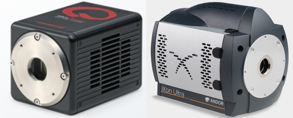 Figure 1: Left: sCMOS Hamamatsu Orca Fusion. Right: EMCCD Andor iXon Ultra.
sCMOS and EMCCD cameras each have their own strengths and weaknesses. For example, CMOS cameras are faster than EMCCD cameras and allow for greater spatial resolution. However, EMCCD cameras are more sensitive and can detect very low signals. They can both be used for most fluorescence microscopy experiments. This document is designed to help you understand which one will give you the best results depending on your sample.
Questions to ask before imaging
· When you are ready to look at your sample, there are a few questions you should ask yourself so that you can have an idea of what your needs are. You may not have an answer to all these questions, of course, but thinking about your image (and future analysis) needs will help steer you onto the correct microscope.
What are you trying to image?
· Is it a live sample or a fixed sample?
· How long will the experiment take?
· How many images are you anticipating?
· What is/are the emission wavelength(s) of your fluorophores(s)?
· How small are the features? How small will the features be after magnification?
· Are you anticipating a strong/bright signal?
Detector specifications to look for
Looking at the spec sheet of available detectors can be daunting and hard to relate to what you really need to achieve with the imaging process. For most fluorescence microscopy experiments, the specifications that will matter most are the following:
· Speed
· Pixel Size
· Dynamic range and bit depth
· Quantum efficiency and readout noise
Principle of operation
Scientific cameras convert light into a digital image by taking advantage of the Photo-Electric effect (Figure 2). In the Photo-Electric effect, Photons absorbed onto silicon dioxide are converted to an electric charge and then transformed into a voltage. The resulting voltage is proportional to the energy of the photons, allowing for a digital image to be created.
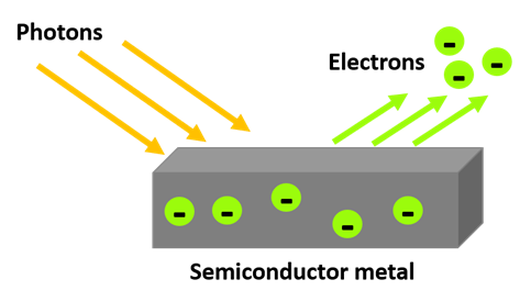
Figure 2: Photo electric effect. The energy of the photons is transferred to the electrons in the semiconductor and charges are released from its surface. Those charges will be converted to a voltage.
The main difference between CCD and sCMOS cameras resides in the process that transforms the electric charge to a voltage (Figure 3).
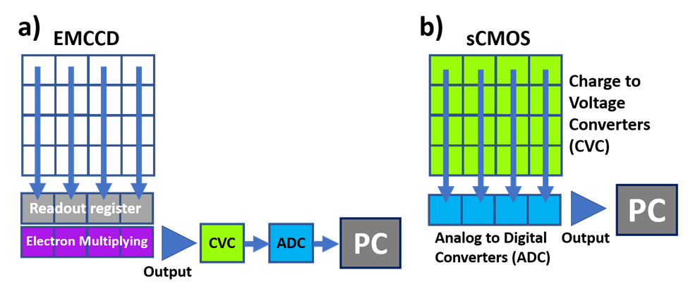
Figure 3: a) EMCCD operation principle. The charges from each pixel are sent to a register, multiplied and converted to a voltage (CVC) and then to a digital signal (ADC) via a single output. b) sCMOS operation principle. Each pixel converts its charge to a voltage (CVC) and each line of pixels is connected to an analog to digital converter (ADC). The output contains a signal already in digital format.
Now that we know how a photon is converted to an electron, and how this is read by the computer, what does EMCCD and sCMOS mean?
- Charge Coupled Devices (CCD) and Electron Multiplying Charge Coupled Device (EMCCD)
In a CCD camera the charge that each pixel receives is transferred via a single channel to be converted into a voltage by a Charge to Voltage Converter (CVC) and then into a digital signal via an Analog to Digital Converter (ADC). This can create a bottleneck of charges and reduces the speed of the detector as every pixel passes through one CVC. An EMCCD operates with the same principle as a conventional CCD but with an extra step to amplify the signal. This electron multiplication (EM) step happens after the readout register, but before the conversion process, and the amount of multiplication can be set by the user.
- scientific Complementary Metal Oxide Semiconductor (sCMOS)
Unlike an EMCCD, each pixel of an sCMOS camera is able to convert its charge to a voltage and acts as a Charge to Voltage Converter, the signal is then converted to digital by row and column to several Analog to Digital Converter. This process allows for much faster speed as it works in parallel. However, sCMOS cameras do not include an electron multiplying (EM) component.
Speed
The differences in operation between an EMCCD and an sCMOS camera result in a major difference in speed. EMCCD cameras can operate at 26 to 56 frames per second and are significantly slower than sCMOS cameras that can operate at 100 frames per second. This is an important factor if your sample is going to be moving very quickly (i.e., diffusing particles) or slowly (i.e., standard cell migration).
Pixel size
The pixel size of a detector matters and is one of the main differences between an sCMOS and an EMCCD camera. If you know the approximate size of the objects you are trying to image and what size they will be after magnification, then you will be able to pick the camera that will resolve your features the best.
sCMOS cameras generally have pixels 6.5µm in size while EMCCD have pixels 13-16µm in size, with both being square in shape. Here, when we say a pixel is 6.5µm, we mean 6.5µm in X by 6.5µm in Y. Both pixel sizes present different advantages:
· Smaller pixels: can resolve smaller features
· Bigger pixels: can accumulate more photons per pixels and are therefore more sensitive even with low signal
The size of the sensor or the total number of pixels does not affect the resolution or sensitivity of the detector, it will dictate how big the field of view can be (the total area that the system can image). EMCCD are typically built with 512x512 pixels while standard sCMOS have 2048x2048 pixels, which results in a much larger field of view.
- What pixel size will be best?
Have you ever heard the word Nyquist, a concept that is frequently mentioned but, when you look online, is difficult to describe? Briefly, Nyquist refers to optimal image sampling to achieve the greatest resolution possible.
Luckily, to optimize your imaging parameters you do not need to know how to explain this concept in a lecture hall, all you need to know is what it means in terms of image sampling.
When you acquire an image using a camera, you are sampling your image by the number and the size of the pixels on your sensor. To obtain an image that looks smooth, the more pixels you have the better. The Nyquist criterion tells you that for a feature to be accurately identified you need at least 3 pixels per feature or in between two features to separate them.
For example, if you are imaging nuclei that are 3µm in diameter with a 10X objective, your nuclei will appear to be 30µm in size on your camera sensor. To accurately resolve these, you will then want at least 3 pixels per 30µm (Figure 4).
· EMCCD with 16µm pixels: 3 pixels is 48µm (3 x 16µm). As such each nucleus will occupy less than 2 pixels and you won’t be able to clearly distinguish them.
· sCMOS with 6.5µm pixels: 3 pixels is 19.5µm (3 x 6.5 µm), each nucleus will occupy about 5 pixels so you will be able to identify them and separate them.

Figure 4: Schematic illustrating the Nyquist criterion. a) Sample with two objects next to each other. b) Resulting image on a sensor with big pixels (for example an EMCCD with 16um pixels). The two objects fall on one pixel and are clumped together as one big blob of light. c) Resulting image on a sensor with small pixels (for example, an sCMOS with 6.5um pixels). The two objects are now identified and separated.
- What happens with binning?
Binning the camera pixels results in larger effective pixels, which can increase the sensitivity and can help with low signals, especially for EMCCDs. Binning also reduces the size of your data and can speed up the acquisition process. For large data sets, this can be very advantageous. However, binning your pixels will affect the sharpness of your image. You may not be able to identify the smaller features of your images anymore because each pixel is larger (Figure 5).
For example, if you have a sCMOS camera with 6.5µm pixels and you apply a 2 by 2 bin, then the pixels will effectively be 13µm. Now the resolving power of your sCMOS will be the same to that of an EMCCD with 13µm pixels.

Figure 5: Argo slide resolution target imaged with a 60X objective and different detectors. Each group of lines contains four lines of decreasing separation from left to right. a) Image obtained with an EMCCD with 13µm pixels. Only Feature 1 (easiest) is fully resolved (the peaks should be above the dashed line to count as resolved). b) Image obtained with an sCMOS with 6.5µm pixels. Features 1 - 4 are fully resolved.
Dynamic range and Bit depth
The dynamic range and the bit depth of a camera are two concepts that are useful to understand as you start imaging.
· The Dynamic Range represents the ratio of the brightest to lowest pixel that the camera can detect.
· The Bit Depth is the number of gray levels that the detector can discern between pure black (0) and pure white (1). Most detectors have a bit depth of 8 bits (28 = 256 gray levels), 12 bits (4096 levels) or 16 bits (65536 levels).
In practice, you want to choose the bit depth of your camera that is the closest to the dynamic range of your sample (not all cameras have this option). The detector may offer up to 16 bits of depth, but if your brightest pixels are only 2000 counts, then most of the possible gray levels are unused. Your image would be more appropriately represented by 12 bits (resulting in 4096 gray levels). The larger the bit depth, the larger the file size. This is important to consider if you are going to capture many images or a video (Figure 6).
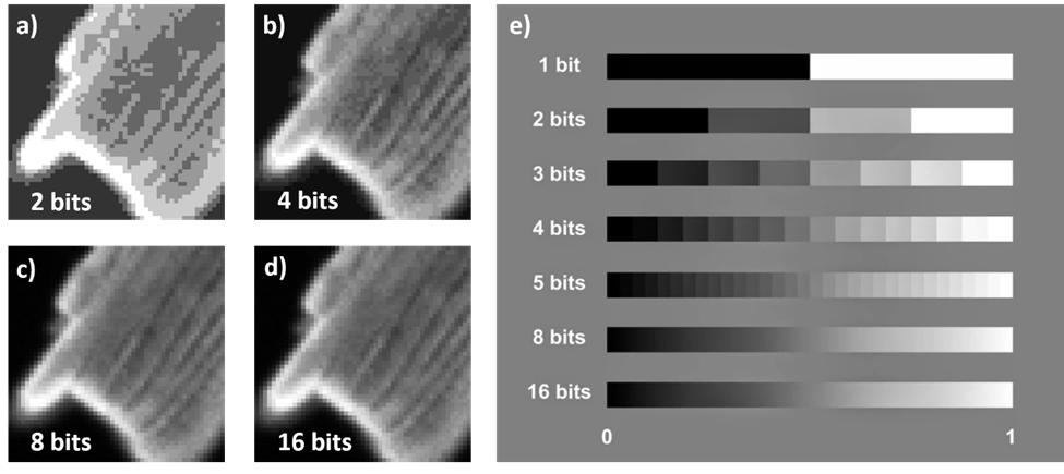
Figure 6: Images represented by varying bit depth. a), b), c), d) BPAE cell with different bit depths. E) number of gray levels between black (0) and white (1) at different bit depths.
- Pixel saturation
Choosing the appropriate bit depth is very important if there is a chance that you may have saturation of some pixels. Saturation happens when too many photons hit a single pixel and exceed the maximum charge it can release. The voltage coming from this pixel is no longer proportional to the intensity of the object and the resulting image no longer accurately represents the data. For example, if you are using a 12 bits detector, the maximum value an individual pixel can report is 2^12 = 4096 counts. (in computer talk, we start counting at 0, so the maximum will be 4095. The range 0 – 4095 = 4096 = 2^12.) If a pixel reports back a value of 4095, you cannot say with confidence that the observed signal was not greater than 4095. It could be more, or even a lot more! As a result, if you have saturated pixels, you cannot quantitatively analyze your image.
- How to recognize pixel saturation?
Your image might be saturated if there are very bright patches when you are in full-scale mode of the Look Up Table (LUT). On the Nikon Elements software, you can ensure you are looking at your image in full scale by bringing the cursor to the end of the bit depth range. For example, if you are using a 16 bits camera, the range of the LUT will be 0 to 65535. When there is saturation the signal goes all the way to the end of the range (Figure 7).

Figure 7: Pixel saturation on a BPAE cell imaged with a 20X objective and visualized on the Nikon Elements software. a) With 100ms exposure the pixels are not saturated, the signal does not reach the end of the Look Up Table (LUT). b) With 1000ms exposure the pixels reach saturation, the signal is at the maximum bit depth.
- How to correct for pixel saturation?
If you have saturation in your image, there are a few things you can do (Figure 8):
· Reduce the power of your light source
· Reduce the exposure time
· Increase the bit depth if you have that option. With a 16 bit camera you can usually avoid saturation by adjusting the power and exposure.

Figure 8: Adjusting parameters on the Nikon Elements software. The binning, exposure and light source power can be adjusted through the interface.
Quantum efficiency and readout noise
The Quantum Efficiency (QE) and the readout noise of the detector also impact the quality of the images you can acquire (Figure 9).
· The Quantum Efficiency is a measure of the number of photons that can be converted into electric charges for each pixel. It is typically above 90% for both EMCCD and sCMOS cameras. However, it depends on the wavelength of the fluorophores you are imaging!
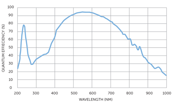
Figure 9: Quantum Efficiency as a function of wavelength. https://www.photometrics.com/learn/imaging-topics/quantum-efficiency
· The readout noise is measured in electrons, it happens during the conversion of the electric charge signal to a digital signal. Both EMCCD and sCMOS cameras achieve a readout noise of less than 1 electron, which is very low.
Summary
|
sCMOS Cameras |
EMCCD Cameras |
|
Higher speed • Good for fast moving samples • 100 frames per second |
Slower speed • Good for slow moving samples • 26-56 frames per second |
|
Higher resolution/Lower sensitivity • Good for small features • 6.5µm pixels • Good for fixed, bright samples • Dim signals may be hard to detect |
Lower resolution/Higher sensitivity • Good for samples with a weak signal or that are light sensitive • 13-16µm pixels • Good for live samples • Can be hard to image dim and bright samples at the same time |
|
Large field of view • Large sensor size: 2048x2048 pixels • Makes very large data files |
Smaller field of view • Sensor size: 512x512 pixels |
|
Binning impact • Smaller data files • Increased speed • Reduced spatial resolution |
Binning Impact • Smaller data files • Increased sensitivity • Increased speed • Reduced spatial resolution |
No Comments