
2. Bruker TruLive3D microscope overview
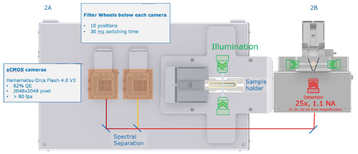
a. The Bruker TruLive3D is a dual sided illumination light sheet microscope. The dual light sheet is projected on the sample by a pair of water immersion 10X 0.3NA microscope objectives. The detection objective is a water immersion 25X 1.1NA objective. An additional magnification changer can be added for a resulting 31.3X and 62.5X. This allows for a resolution down to 255nm in xy.
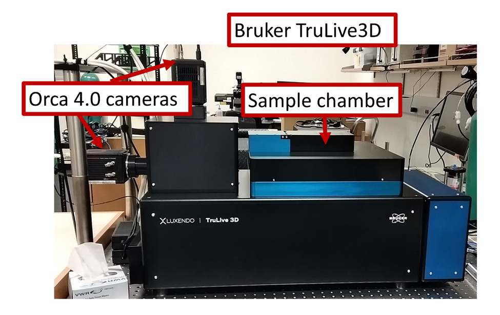
The images are acquired on two Orca Flash 4.0 cameras. Each camera has a motorized filter wheel on its path. Through a combination of dichroics and filters the long wavelengths are directed to one camera (the horizontal one) and the short wavelengths to the other (the vertical one).
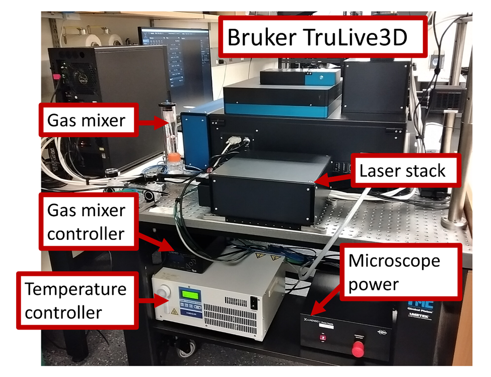
b. On the back of the microscope you will find the laser stack on the table, the 4 laser lines are launched in an optical fiber plugged into the microscope. The gas mixer and humidifer is found right next to the microscope. In case the water level in the column is low, refill using sterile DI water only. The green line is for the CO2, the blue for the air and the yellow line for nitrogen in case someone needs it. The gas mixer controller is the black box located on top of the white temperature controller. On the right is the microscope system power supply. In case of emergency, turn off everything with the big red button.
The figure below is a schematics from Bruker showing how the sample is imaged by the Light-Sheet. Your sample should be sitting at the bottom of the little cuvettes that have to be used as sample holders.

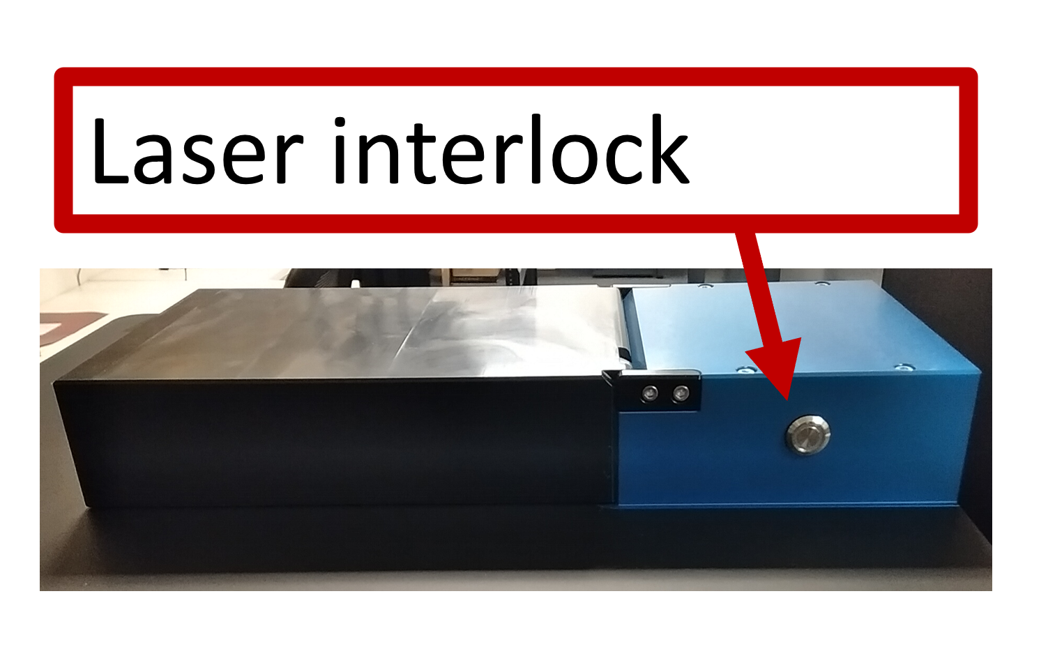
c. Every time you open the sample chamber the lasers will turn off automatically. When you close the lid, always remember to press the interlock button on the back of the sample chamber.
d. When you open the sample chamber, you will see a lens on the lid. This is for illumination with an LED light, directly above the sample. It is used to find the sample. In the sample chamber you will see the detection objective at the bottom and the illumination objectives on the sides. The sample will be held in the metal brackets that are attached to the translation stage.

A more comprehensive schematic of the sample chamber can be found on the Bruker TruLive3D manual accessible on the Luxendo computer and is reproduced here:
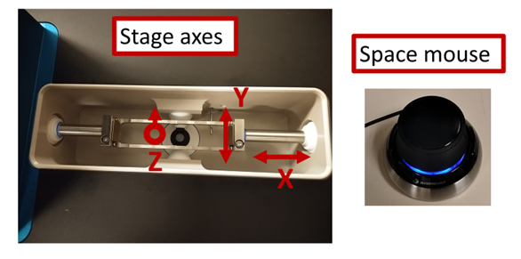
e. The translation stages can be controlled with the Luxendo software or with the space mouse. The Z direction is up and down in the direction of the detection objective. X is the direction along the sample and Y is the direction across the sample, along the illumination path.
No Comments