
4. Bruker Trulive3D calibration
Calibration of the laser beams is critical for optimal imaging and should be done prior to every experiment.
If you are using the temperature controller you should wait that the temperature in the sample chamber is close to the set value to perform the calibration as temperature is one of the main factors that can change the beams alignment.
NOTE: We found that it is best to install the sample in the sample chamber and let it sit a little bit before performing the calibration. The calibration is done in the water under the sample. Having the sample already in place prevents any changes in temperature when opening the chamber to install the sample.
Install the sample in the sample holder and into the sample chamber. Hold it at one end and push the other end against the end o the brackets then press the other end into place.
On the left side click on the Calibration tab.
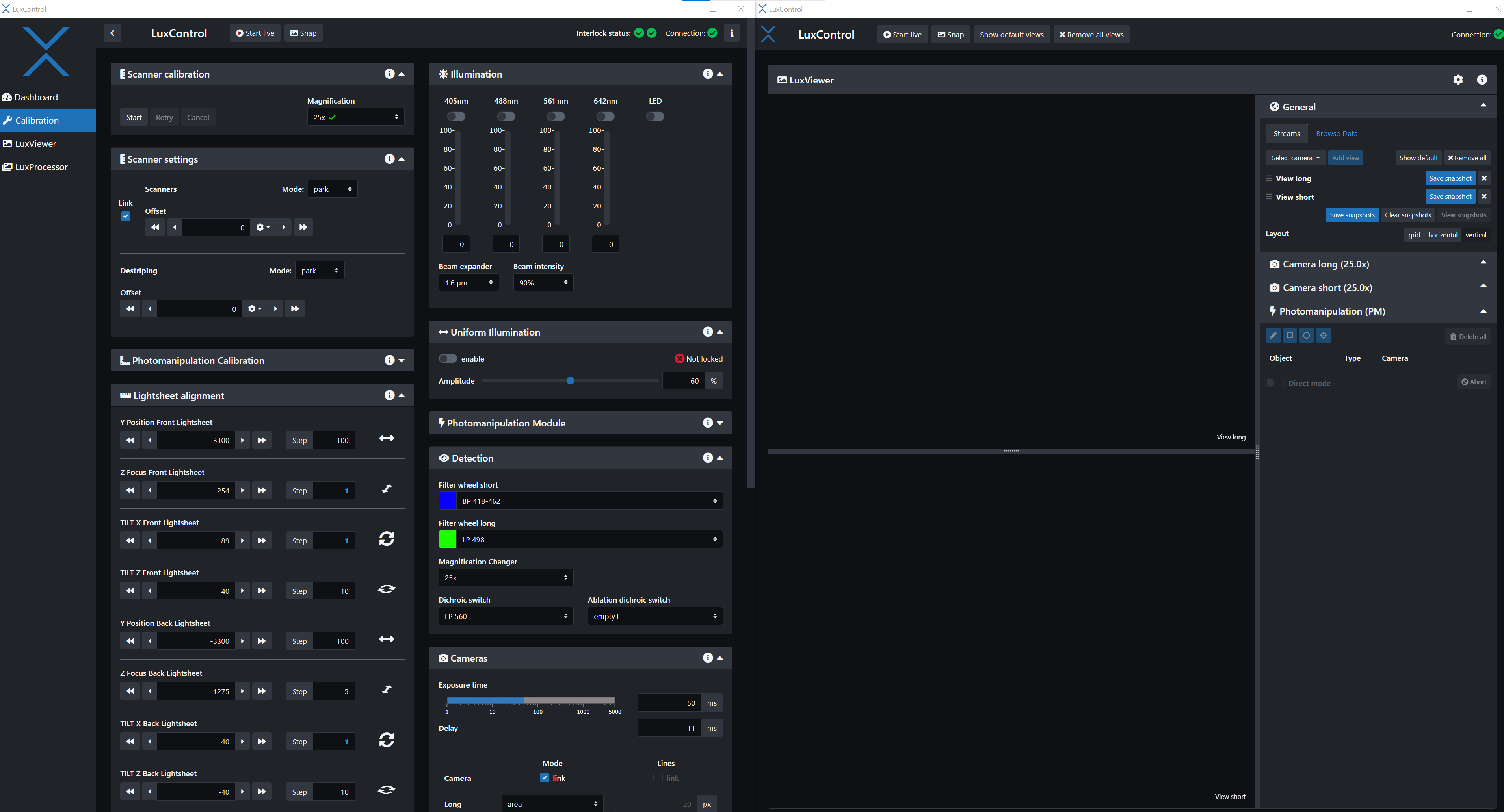
Below is a view of the calibration page as it first appears.
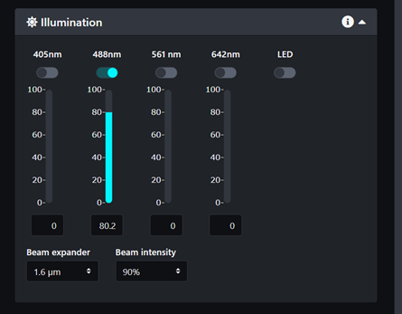
To observe the beams and align them you want to have water in the sample chamber. You can turn on any of the laser lines but in pure water, only the 488nm laser will produce enough scattering to be observed.
Select the beam intensity at 90% and turn on the 488nm laser to about 50% or above.
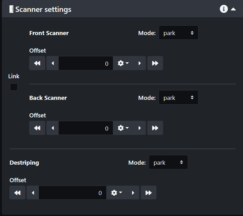
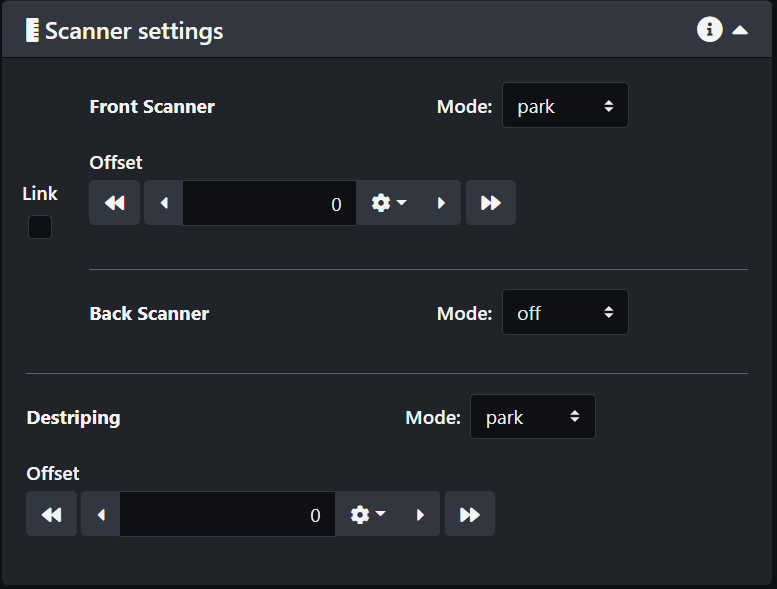
The next thing you need to do is to unlink the scanners so you can control the beams separately. Select the option "park" for both beams and check the camera display.
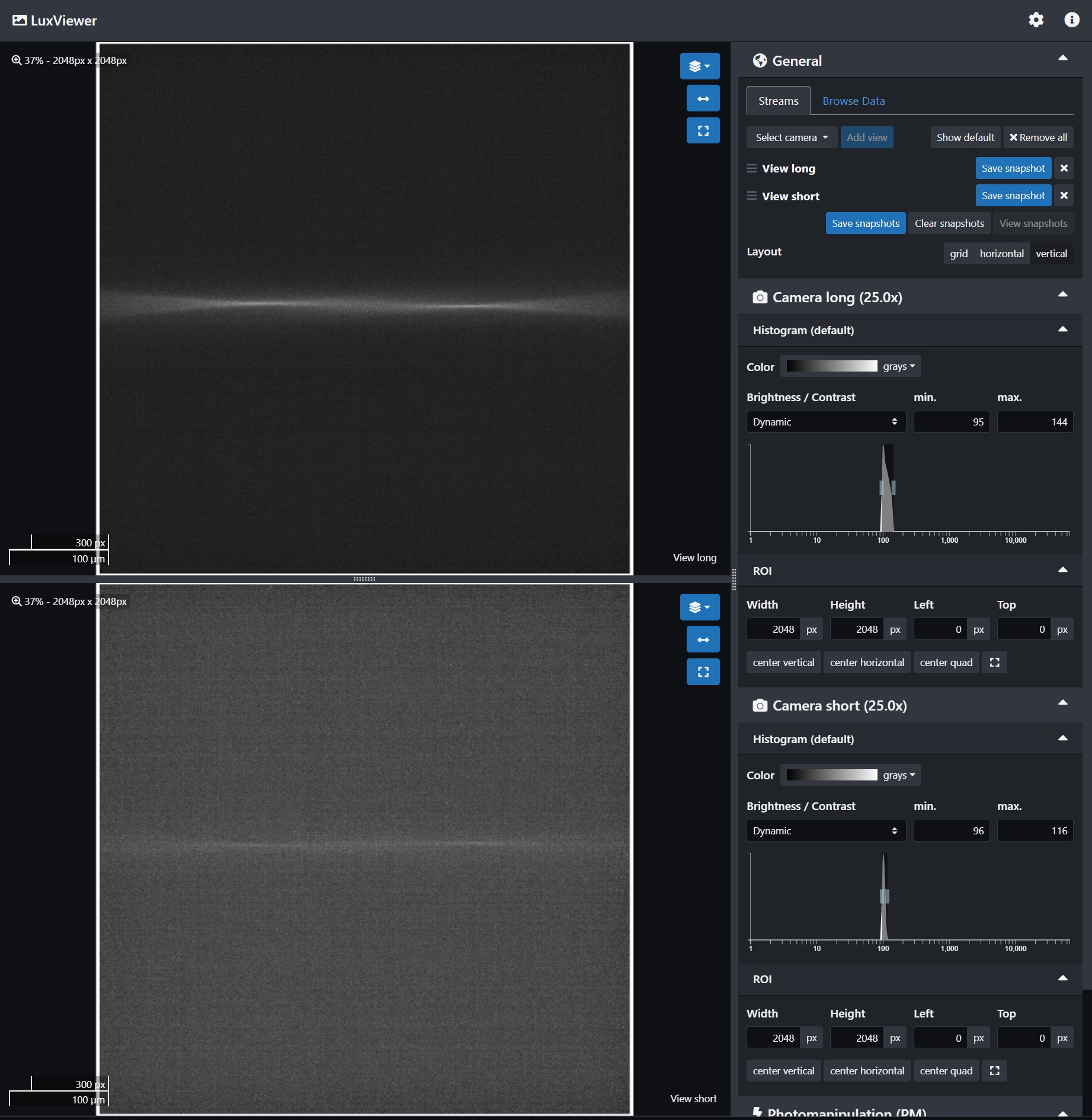
When both cameras are connected you will see the same image from two different angles. The beams may look fuzzy and not in line as in the image below. If they are too dim, try increasing the laser power or the camera exposure time. They may also be far out of focus.
Calibration is better done one beam at a time. Start with the front scanner and then repeat for the back scanner. Go in the scanner settings and select "off" for the back scanner.
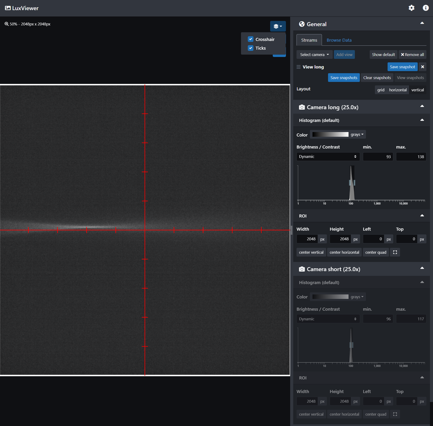
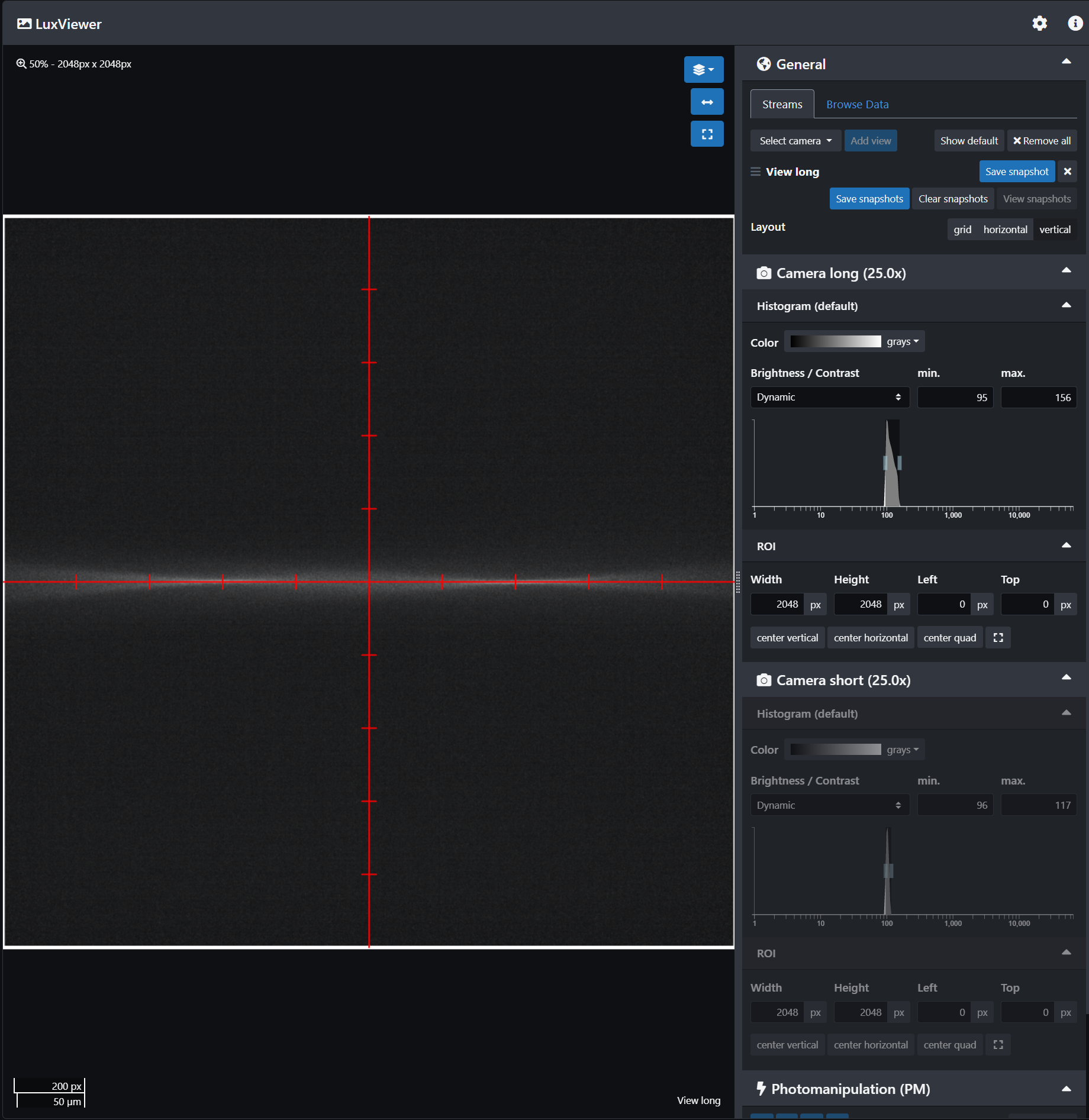
Now only the front beam will be displayed. In order to align it you can use the Crosshair and Ticks markers. You also don't need to have both cameras connected, it makes it easier to have only one image displayed. On the screenshot below, the beam is slightly offset with respect to the crosshair and not very sharp. You will want the beam to be uniformly centered on the line and the center of the beam aligned with the second tick from the center, at least for most experiments.
Offset correction: Go in the scanner settings and change the offset value until the beam is perfectly aligned with the crosshair. It usually requires small values between 0 and 0.1. Once you are satisfied with the result click on the store button next to the offset value. This will save the value through the experiment.

Z focus adjustment: In the stage control, select the Z Front Lightsheet and adjust the value until the beam is as crisp as possible with a narrow waist.
Y position adjustment: In the stage control, select the Y Front Lightsheet and adjust the value until the middle of the beam is on the second tick from center.
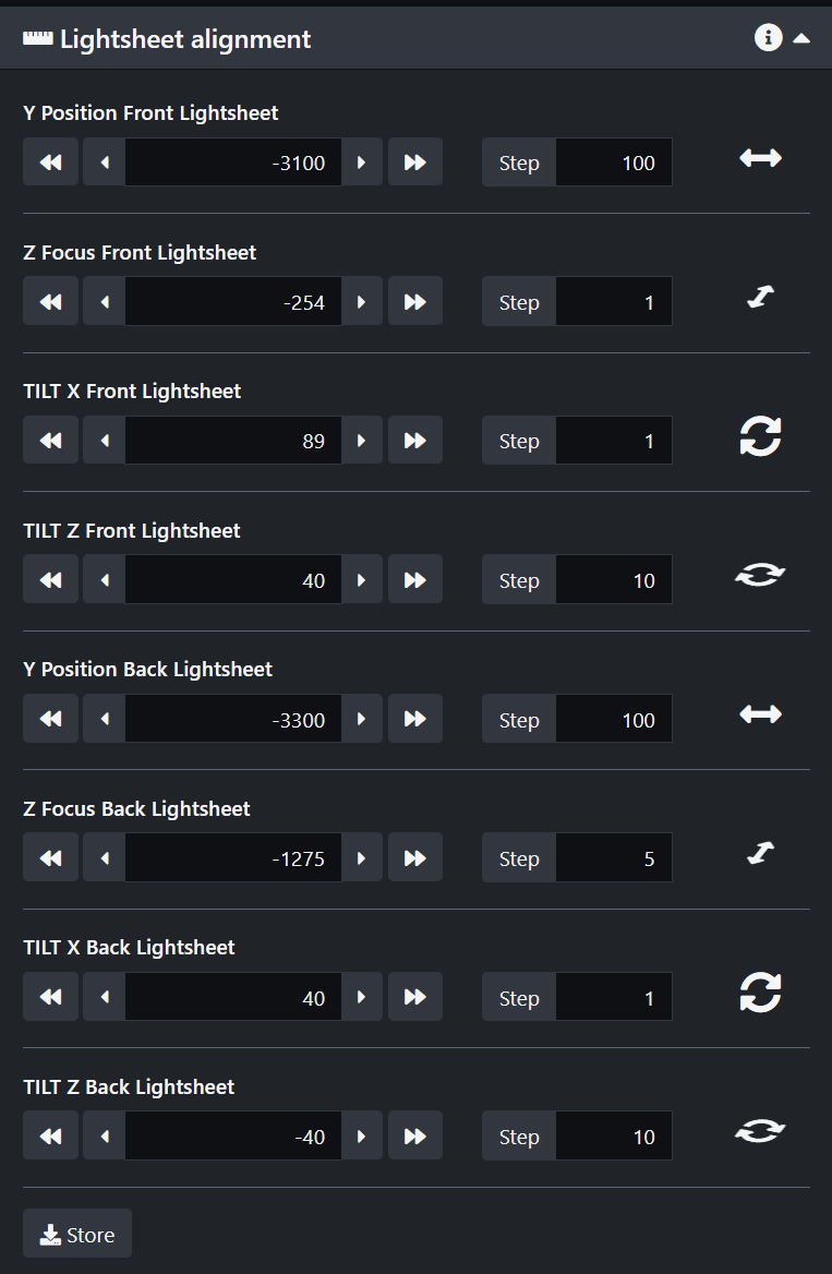
The last two parameters to adjust are the In-plane tilt "Tilt X Front Lightsheet" and Out-of-plane tilt "Tilt Z Front Lightsheet". To better visualize them you can turn the TAG Lens on.

In-plane tilt adjustment "Tilt X": Change the value until the beam is perfectly centered along the crosshair.
Out-of-plane tilt adjustment "Tilt Z": you want to observe a uniform thickness of the beam along the crosshair. Change the value until it looks the most uniform.
Store all the values by clicking on the save button at the bottom of the Lightsheet alignment panel.
Repeat the process for the back scanner. Turn the front scanner off and park the back scanner then adjust the offset, the Z, Y, In-plane tilt and Out-of-plane tilt. Remember to turn off the TAG lens to start the procedure and turn it back on the adjust the in-plane tilt and out-of-plane tilt. Save your values and park both beams to check they are both well aligned.
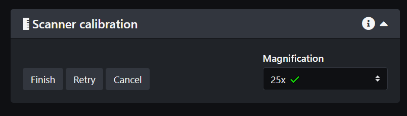
The last step of the basic calibration process is to perform the Scanner Calibration.
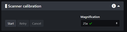

Make sure both cameras are connected. Then click start and click on the next steps until the calibration is finished. Click Finish and if successful you are good to go!
NOTE 1: If you are planning to use more than one magnification you should repeat the scanner calibration for each magnification.
NOTE 2: If you need to perform photo-manipulation you will need to calibrate the PM module as well. Instructions will be detailed in the Photo-Manipulation page.
Cameras alignment
In the event that the short camera is shifted with respect to the long camera, we can correct for it.
- Use a sample with features stained for long wavelengths emission and short wavelengths emissions. Beads are ideal for this.
- Check that the beads are in focus on both cameras. If one channel looks slightly out of focus, use the "camera alignment" tab in the calibration panel to adjust the focus.
- Center one bead exactly at the center of the cross-hair marker on the long camera.
- Use an allen key from the Bruker tool kit to manually adjust the short camera using the knobs at the base of it until the same bead is centered on the short camera too.
No Comments