
Nikon A1R - Mode of operation
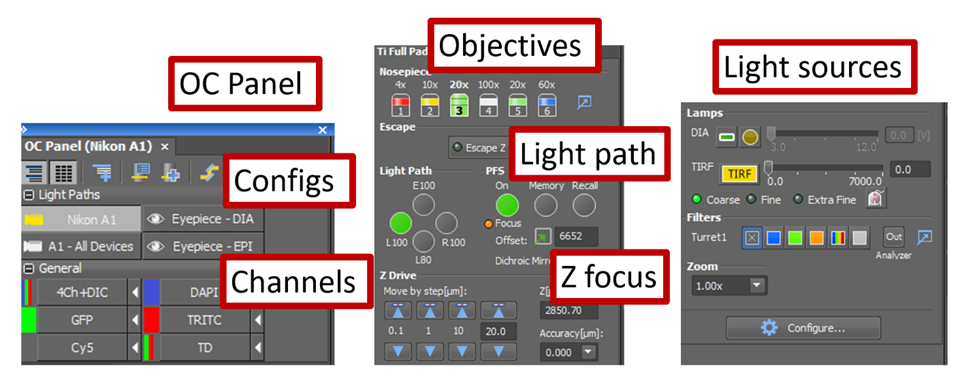
Overview of the OC (Optical Configuration) control panel
The OC Panel contains the different light source configurations. You will principally use the Nikon A1 configuration for the laser scanning with the Nikon PMT as a detector. The DIA (diascopic transmitted light) configuration can be used to find the sample in widefield mode if needed. The EPI configuration is for basic epifluorescence mode which is not really in use on this microscope anymore.
Just below is the selection of channels. Select the channel that corresponds to your fluorophores.
The Ti Full Pad allows you to choose the objective you need, orient the light path to the detector (here it is on the right port) and adjust the focus with the software.
The Lamps section has the controls for the LED lamp (DIA) and the laser (TIRF) if used in epifluorescence mode (no scanning). The TIRF option comes from a previous use of this microscope and you will not likely need it when you come to use the A1R. The filters are automatically changed when you choose a fluorescence channel so you do not need to change anything there.
Scan acquisition
At this point in your training it was time to look at the sample and start an acquisition. We used a demo sample with the 20X objective, air immersion. If you are using the 100x oil immersion objective, start by dropping a drop of oil on the top of the objective, as described in this tutorial video by Dr. Dragavon.
Now that you have delicately placed your sample on the sample plate holder you need to:
-
Bring the sample into focus
- Press the PFS button on the microscope base. You will hear several beeps and the light will start blinking, indicating that the microscope is searching for the focal plane.
- Raise the objective slowly using the black knob on the side of the joystick or on the sides of the microscope until you hear a beep. The sample is now very close to be in focus. The objective won’t move any further with the knob on the side of the joystick or the knobs on each side of the microscope. At this point you need to be looking at the sample in order to find the focal plane. Select a channel that corresponds to fluorophores present in your sample.
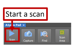
- Click the blue arrow in the “A1plusPad” to start a scan.
- To visualize the sample, first auto scale the Look Up Table then slowly turn the PFS knob until you find the sample and focus on the plane you want.
This button will auto-scale the Look Up Table for the current image and the current channel. 
Optimizing the image
-
Scan mode
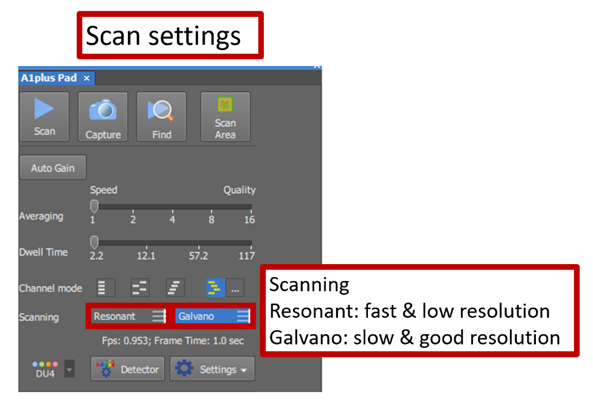
The A1plus Pad allows you to define the scan settings. There are two scanning options: Resonant and Galvano. Resonant scanning is fast and very useful to find the sample as you adjust the focus. However, the resolution is not very good. Once you found your sample, it is recommended to use Galvano scanning. This mode is much slower but has a higher resolution.
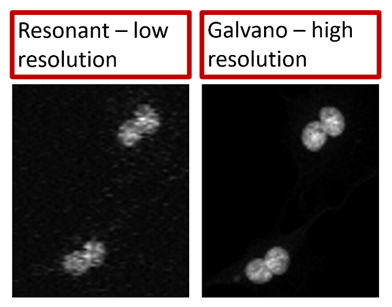
The following figure illustrates the difference in resolution between the resonant and the galvano scanning modes.
-
Understanding the Look Up Table (LUT)
The Look Up Table on the laser scanning confocal is similar to the Look Up Table of a camera.
As you turn on the different channels, their look up table will display on the software. When a laser is on, you can modify its power which will affect the signal.
To auto-adjust the lookup tables, clicking on the Auto Scale buttons above the image of interest.
 This button will adjust the lookup table for each frame (useful in live view mode)
 This button will adjust the lookup table for the current image
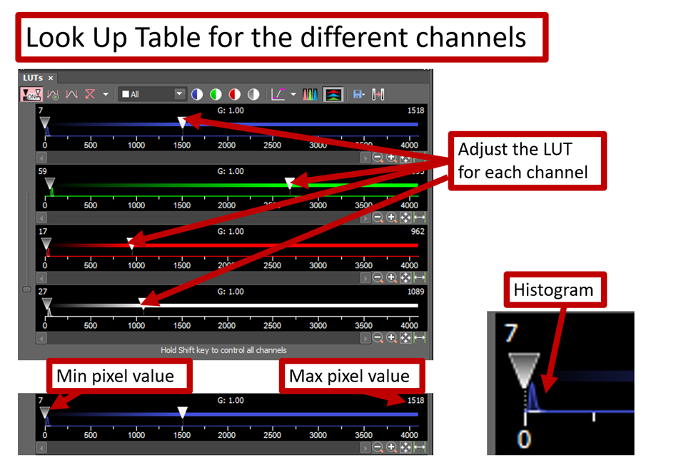
The different channel in the A1plusPad can be turned on or off and the laser power can be modified.
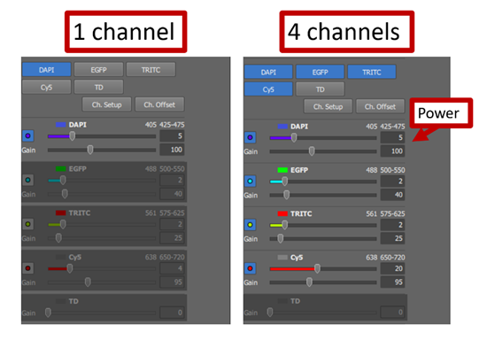
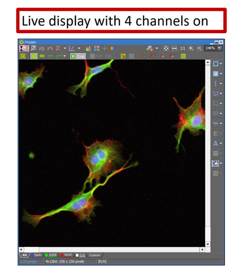
When you have multiple channels on, you will see the image reconstruct in different colors. Before saving anything, you can adjust the brightness of each channel by changing the power of their corresponding laser so that you have a good signal for each of them.
-
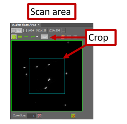
Define the scan area
The scan area is displayed at the bottom of the A1plusPad. You can change the size of the scan area by changing the number of pixels or by cropping it.
-
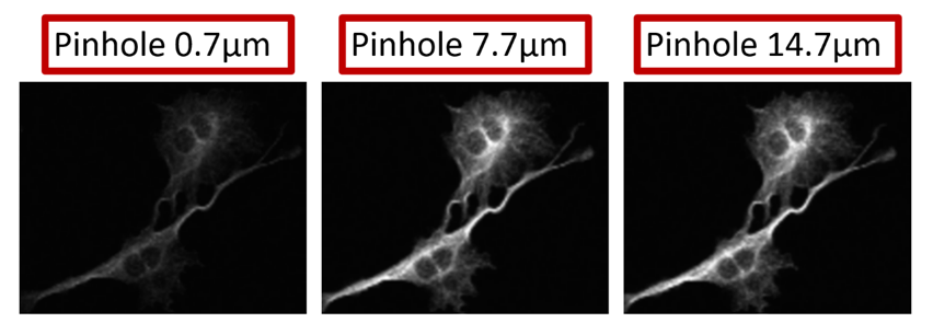
Understanding the effect of the pinhole size
The laser scanning confocal has an adjustable pinhole. Closing it results in higher resolution in z but a lot less signal. At its bigger opening you will have more light hitting the PMT but a smaller step size in z.
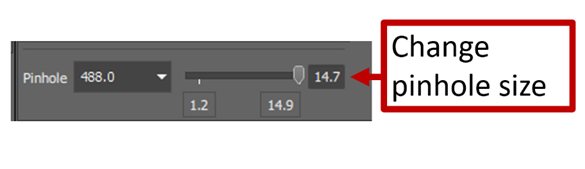
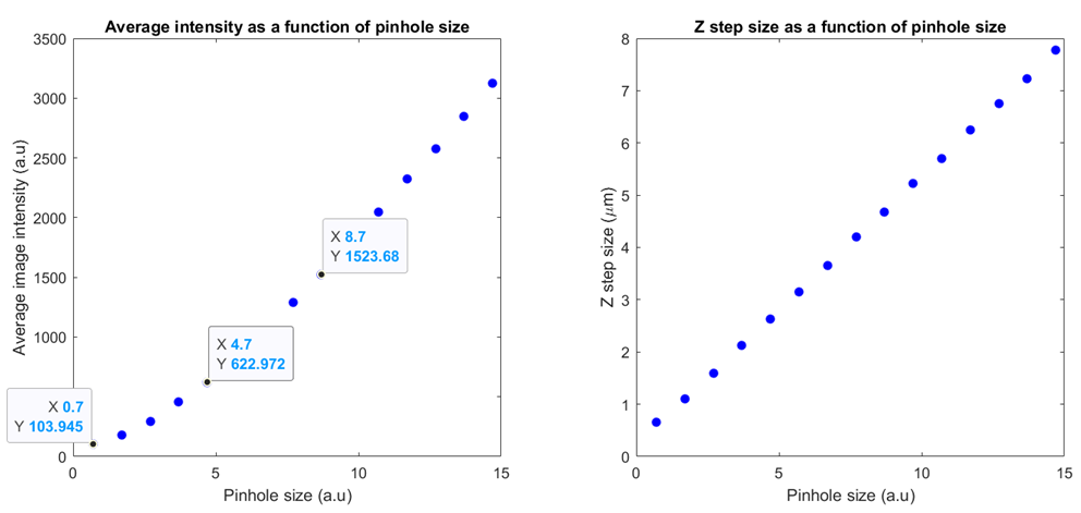
The following plots show the average intensity of an image as a function of the pinhole size and the z step size as a function of the pinhole size. The sample is fluorescin in a dish and we measure the average intensity over the whole image.
-
Selecting an interesting area of your sample
Now that you found the sample, brought it in focus and optimized its signal, you may want to select a specific cell and center it in the image. You can always do this using the joystick of course. But there is another useful way to perfectly center the cell you choose. If you right click on the image viewer where the cell is located you can find the option to center it and the stage will move accordingly.
Another useful feature of Nikon Elements is the option to save your field of view in the image format of your choice. This will be a view only image, it won’t allow you to process the different channels separately and such. But you may find this useful to show your colleagues or for later comparison with other data sets. To do so, click on the “x” letter on the keyboard and you will find the option to save in the format of your choice.
Image acquisition and saving
The Nikon Elements software offers many options for acquiring and saving your data. For A1R experiments you will typically want to acquire a z-stack and possibly for different channels at different wavelengths.
-
Assign settings
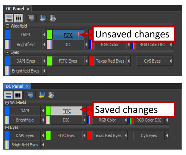
Before you start acquiring and saving data, you need to assign the settings you chose. When you open the software, each channel is set at its default settings. After finding your sample, you probably changed some settings so that the image looks as good as it can.
You should see a little “!” in the corresponding channel buttons. Click on the arrow next to it to assign the settings. When the “!” mark disappears your changes should be saved and you are ready to move on to the acquisitions.
-
Acquiring a z-stack image for different channels
In the ND Acquisition Panel, check the box to “Save to File” and choose your destination and filename.
a. To acquire a time lapse image stack, you need to check the box that says Z and the box that says λ.
b. Then you can define your acquisition settings for Z: number of steps, start and end point, range, step size and order of acquisition.
c. Define the acquisition settings for the different wavelengths. You need to choose a configuration for each channel (those are pre-set in the software).
d. After you defined all the settings, click “Order of Experiment” to define in which order you want the scan to proceed.
e. When you are ready to image click “Run now”
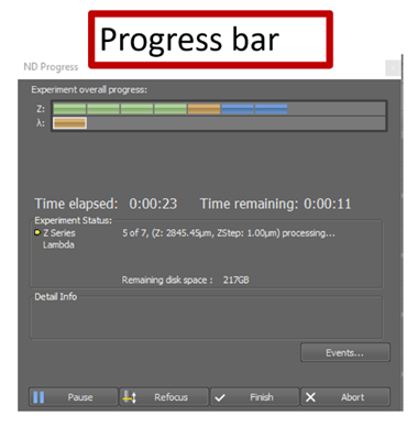
While the scan is in progress you will see this window:
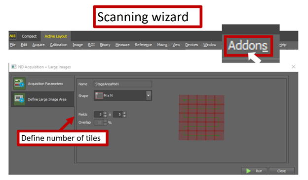
Finally, you can use the scanning wizard to tile several scan areas together. This option is found in the Addons menu. Select “Scanning wizard”. You can find options for the scan there, define the number of tiles and in which order the scan goes.
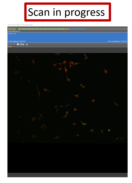
While the scan is in progress you can see the tiles appear in the order selected in the scanning wizard.
No Comments