Nikon A1R Laser Scanning Confocal
- Nikon A1R - Overview
- Nikon A1R - Basic setup
- Nikon A1R - Moving the sample
- Nikon A1R - Mode of operation
- Shut Down and clean up procedures
- Using the Perfect Focus System (PFS)
- Online learning resources by Nikon
Nikon A1R - Overview
Basics of laser scanning confocal
A laser scanning confocal microscope produces high resolution images of 3D samples of up to 15 microns. It operates using pinholes on the laser beam path, blocking the out of focus light from the specimen. Images are acquired point by point with a PMT (Photo Multiplier Tube) while scanning the laser beam. Each point will be reconstructed as one pixel of the resulting image.
The size of the pinhole (circular aperture) can be modified. When the pinhole is open to its maximum the detector receives more light and the reconstructed image will be brighter but the resolution will be lower. On the other hand, when the pinhole is at its minimum the reconstructed image will be dimmer but with higher resolution.
Laser scanning confocal microscopy is ideal for fixed samples 5 to 15 microns thick, it achieves very good optical sectioning. Scanning the laser beam is a slow process and therefore not appropriate for all live samples. Image reconstruction is done in the image viewing software.
Nikon A1R parts
The Nikon A1R microscope operates with several different laser lines (405nm, 488nm, 561nm, 638nm) all combined into an optical fiber. The laser output is then scanned with a galvanometer (a mirror electronically controlled) or a piezo-electric device (resonant mode) and goes through the pinhole and microscope objective before reaching the sample.
Two types of detectors are used:
Nikon PMT for the 400-500nm range
GaAsp PMT for the 500-600nm range
There is the option to use an Okolab stagetop incubator with CO2, temperature and humidity controls.
Nikon A1R - Basic setup
This guide describes how to turn on the microscope and mount your sample on the microscope.
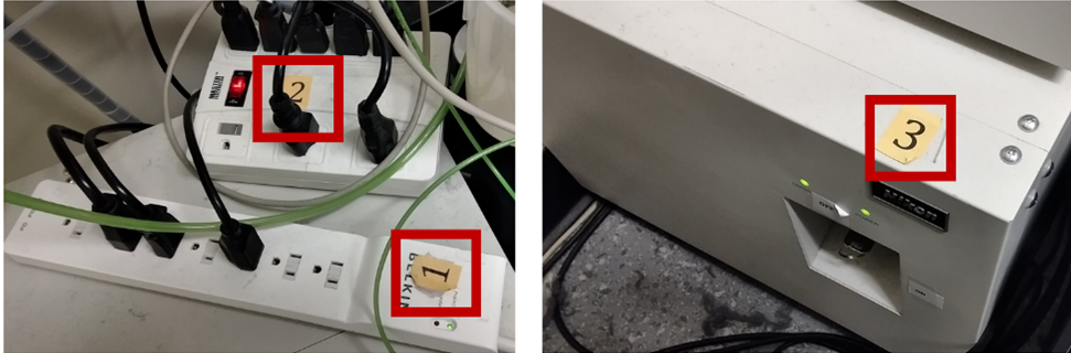
- If the microscope is off, turn on the microscope (the following protocol is also taped to the wall):
- Turn on power strip 1.
- Turn on power strip 2.
- Turn the key on the laser box labeled 3 to the ON position (right).
- Turn on the computer

- Start Nikon Elements by clicking on the icon on the desktop.

- Wait for Elements to start up and the optical configurations to import successfully.

Note: If an error occurs, please contact us. The microscope will likely not work if the configurations are not imported correctly. - Using the Elements software, click on the objective you plan to use an wait for the microscope to finish switching.
- If you are using the 100x oil objective, add a single drop of oil (watch video).
IMPORTANT: Only add oil to the 100x objective. Oil on the air objectives could result in damage. If a mistake happens, please email us immediately so we can clean the objective.
- If you are using the 100x oil objective, add a single drop of oil (watch video).
- Insert the appropriate sample plate holder. You should choose the appropriate holder depending on the imaging plate you are using (slide, 96-well plate, round dish holder).
- Mount your sample on the holder (the picture below shows a slide mount). Make sure the cover slip is facing downwards. If there are any oil stains on the equipment please clean up with ethanol before starting your experiment.

- You are now ready to image. Please read the following pages on setting up the perfect focus system (PFS) and acquiring an image.
-
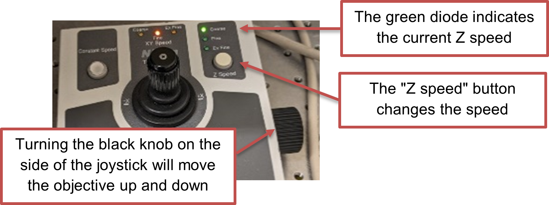
To control the microscope stage, you will use the joystick. The central knob controls the X and Y directions, you can change the speed by twisting the top of it.
The knob on the side of the joystick can be used to lower or raise the objective and bring the sample into focus. You can also do this by using the two knobs on each side of the microscope itself.


Nikon A1R - Moving the sample
The microscope contains a motorized stage which moves the sample. The stage is controlled using the joystick. The sections below describe how to move the sample in XY and Z directions.
XY position
The XY position of the stage can be controlled by using the joystick or by right-clicking on the image and selecting “Move this point to center”.
If you are using the joystick, the speed of the stage movement can be changed by either:
- Rotating the top of the joystick. This will change the stage speed from Coarse (Fastest) > Fine > Extra Fine (Slowest).
- The speed of the stage is also controlled by the angle of the joystick. Pushing on the joystick further moves the stage faster.

Z position
The position of the objective is controlled by the z-position of the microscope. This changes the focus of the sample.
- The black knob on the right of the joystick will move the objective up and down.
- The speed at which the z-position changes can be controlled by pushing the "Z speed" button. This will change the z-position speed from Coarse (Fastest) > Fine > Extra Fine (Slowest).
- If the z-position does not change, check that the PFS is not engaged. To change the focus when the PFS is engaged, use the Perfect Focus wheel.
Nikon A1R - Mode of operation
Overview of the OC (Optical Configuration) control panel
The OC Panel contains the different light source configurations. You will principally use the Nikon A1 configuration for the laser scanning with the Nikon PMT as a detector. The DIA (diascopic transmitted light) configuration can be used to find the sample in widefield mode if needed. The EPI configuration is for basic epifluorescence mode which is not really in use on this microscope anymore.
Just below is the selection of channels. Select the channel that corresponds to your fluorophores.
The Ti Full Pad allows you to choose the objective you need, orient the light path to the detector (here it is on the right port) and adjust the focus with the software.
The Lamps section has the controls for the LED lamp (DIA) and the laser (TIRF) if used in epifluorescence mode (no scanning). The TIRF option comes from a previous use of this microscope and you will not likely need it when you come to use the A1R. The filters are automatically changed when you choose a fluorescence channel so you do not need to change anything there.

Scan acquisition
At this point in your training it was time to look at the sample and start an acquisition. We used a demo sample with the 20X objective, air immersion. If you are using the 100x oil immersion objective, start by dropping a drop of oil on the top of the objective, as described in this tutorial video by Dr. Dragavon.
Now that you have delicately placed your sample on the sample plate holder you need to:
-
Bring the sample into focus
- Press the PFS button on the microscope base. You will hear several beeps and the light will start blinking, indicating that the microscope is searching for the focal plane.
- Raise the objective slowly using the black knob on the side of the joystick or on the sides of the microscope until you hear a beep. The sample is now very close to be in focus. The objective won’t move any further with the knob on the side of the joystick or the knobs on each side of the microscope. At this point you need to be looking at the sample in order to find the focal plane. Select a channel that corresponds to fluorophores present in your sample.
- Click the blue arrow in the “A1plusPad” to start a scan.

- To visualize the sample, first auto scale the Look Up Table then slowly turn the PFS knob until you find the sample and focus on the plane you want.
This button will auto-scale the Look Up Table for the current image and the current channel. 
Optimizing the image
-
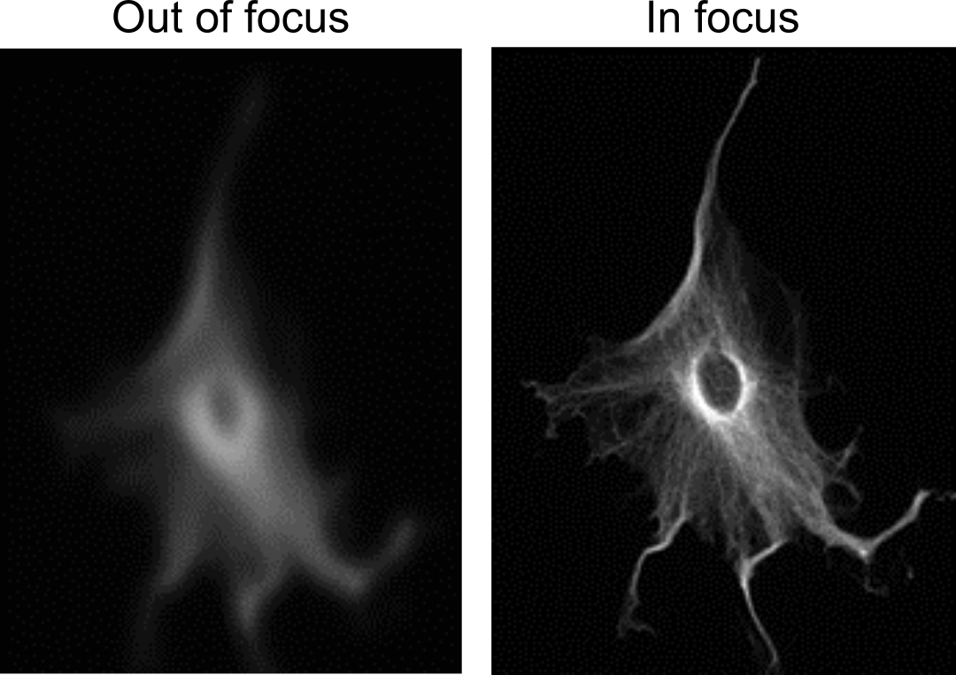
Scan mode
The A1plus Pad allows you to define the scan settings. There are two scanning options: Resonant and Galvano. Resonant scanning is fast and very useful to find the sample as you adjust the focus. However, the resolution is not very good. Once you found your sample, it is recommended to use Galvano scanning. This mode is much slower but has a higher resolution.

The following figure illustrates the difference in resolution between the resonant and the galvano scanning modes.

-
Understanding the Look Up Table (LUT)
The Look Up Table on the laser scanning confocal is similar to the Look Up Table of a camera.
As you turn on the different channels, their look up table will display on the software. When a laser is on, you can modify its power which will affect the signal.
To auto-adjust the lookup tables, clicking on the Auto Scale buttons above the image of interest.
 This button will adjust the lookup table for each frame (useful in live view mode)
This button will adjust the lookup table for the current image

The different channel in the A1plusPad can be turned on or off and the laser power can be modified.

When you have multiple channels on, you will see the image reconstruct in different colors. Before saving anything, you can adjust the brightness of each channel by changing the power of their corresponding laser so that you have a good signal for each of them.

-
Define the scan area
The scan area is displayed at the bottom of the A1plusPad. You can change the size of the scan area by changing the number of pixels or by cropping it.

-
Understanding the effect of the pinhole size
The laser scanning confocal has an adjustable pinhole. Closing it results in higher resolution in z but a lot less signal. At its bigger opening you will have more light hitting the PMT but a smaller step size in z.


The following plots show the average intensity of an image as a function of the pinhole size and the z step size as a function of the pinhole size. The sample is fluorescin in a dish and we measure the average intensity over the whole image.

-
Selecting an interesting area of your sample
Now that you found the sample, brought it in focus and optimized its signal, you may want to select a specific cell and center it in the image. You can always do this using the joystick of course. But there is another useful way to perfectly center the cell you choose. If you right click on the image viewer where the cell is located you can find the option to center it and the stage will move accordingly.
Another useful feature of Nikon Elements is the option to save your field of view in the image format of your choice. This will be a view only image, it won’t allow you to process the different channels separately and such. But you may find this useful to show your colleagues or for later comparison with other data sets. To do so, click on the “x” letter on the keyboard and you will find the option to save in the format of your choice.
Image acquisition and saving
The Nikon Elements software offers many options for acquiring and saving your data. For A1R experiments you will typically want to acquire a z-stack and possibly for different channels at different wavelengths.
-
Assign settings
Before you start acquiring and saving data, you need to assign the settings you chose. When you open the software, each channel is set at its default settings. After finding your sample, you probably changed some settings so that the image looks as good as it can.
You should see a little “!” in the corresponding channel buttons. Click on the arrow next to it to assign the settings. When the “!” mark disappears your changes should be saved and you are ready to move on to the acquisitions.

-
Acquiring a z-stack image for different channels
In the ND Acquisition Panel, check the box to “Save to File” and choose your destination and filename.
a. To acquire a time lapse image stack, you need to check the box that says Z and the box that says λ.
b. Then you can define your acquisition settings for Z: number of steps, start and end point, range, step size and order of acquisition.
c. Define the acquisition settings for the different wavelengths. You need to choose a configuration for each channel (those are pre-set in the software).
d. After you defined all the settings, click “Order of Experiment” to define in which order you want the scan to proceed.
e. When you are ready to image click “Run now”
While the scan is in progress you will see this window:

Finally, you can use the scanning wizard to tile several scan areas together. This option is found in the Addons menu. Select “Scanning wizard”. You can find options for the scan there, define the number of tiles and in which order the scan goes.

While the scan is in progress you can see the tiles appear in the order selected in the scanning wizard.

Shut Down and clean up procedures
When you are done imaging, remove your sample from the microscope and place it on a kimwipe or other paper towel if it has oil or water.
If you used an oil objective, please refer to the instructions of Dr. Dragavon to clean it.
Shut down the system according to the shut-down procedure taped on the wall:
A. Save your beautiful images to your shared drive.
B. Exit Nikon Elements and disconnect from your shared drive.
C. Remove your sample from the stage and clean up the microscope (remove oil from the objective, shutdown the environmental chamber…). Manually lower the objective to a position below 1000 on the LCD screen.
D. Open the reservation calendar. If there is a user within 2 hours of your session, proceed to F. If the user is more than 2 hours after your session, proceed to Step E.
E. Turn the key on the laser box to the LEFT (3).
F. Turn off the two power strips (1 and 2).
G. Publish an awesome article.
Using the Perfect Focus System (PFS)
The perfect focus system locates the coverslip and continually adjusts the objective height to follow any drift in the system.
Engaging the PFS
- Only if using the 100x oil objective, first raise the objective by turning the z-axis control until the oil contacts the sample. This step is not necessary for the air objectives.
- Starting the PFS before the oil contacts the sample could result in an incorrect focus being acquired. If this happens, turn off the PFS and start again.
- Starting the PFS before the oil contacts the sample could result in an incorrect focus being acquired. If this happens, turn off the PFS and start again.
- Press the PFS button on the microscope base. You will hear several beeps and the light will start blinking, indicating that the microscope is searching for the focal plane.
- Raise the objective slowly until you hear a beep using the black knob on the right side of the joystick. The PFS button will be solidly lit when perfect focus is engaged correctly and the LED next to the FOCUS display will be lit. Be careful not to push the objective into your sample - this will damage the objective and lead to costly repairs.
- The display on the LCD screen on the microscope base indicates the Z position of the objective. The typical Z-position is between 2000-3000 µm.
- If you turn the knob the wrong way (i.e., lowering the objective), you might hear a continuous tone. This is fine - you just have to reengage the PFS system by pressing the button.
- If you are having trouble getting perfect focus to engage, see Troubleshooting Perfect Focus below.
- The display on the LCD screen on the microscope base indicates the Z position of the objective. The typical Z-position is between 2000-3000 µm.

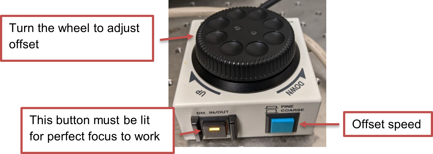
Refining the perfect focus offset
Once perfect focus is engaged, you cannot change the z-position of the microscope. However, to get cells in focus, you can change the perfect focus offset using the perfect focus wheel.
- Start Live View.
- Adjust the perfect focus offset by rotating the perfect focus wheel.
- The blue button can be used to change the offset change speed. When the button is pressed in, turning the wheel changes the offset a little bit. When the button is out, the turning the wheel changes the offset a lot. You should start with coarse adjustment until you start to see some cells, then switch to fine.
- When the cells are in focus, click on the
 button next to the selected optical configuration to save the settings.

Troubleshooting tips
- The perfect focus system looks for a reflection off the coverslip. This can be formed by a glass-air or a glass-water (e.g. sample mounted under an agar pad) boundary. If your sample is fixed with mounting media, the perfect focus will not work.
- Check that the coverslip is facing downwards towards the objective. The coverslip thickness should be no thicker than 1 mm.
- Are you using the correct objective? Did you add oil to an air objective or forget the oil for the 100x objective? If the latter is true, clean the oil off and let Joe know asap.
Online learning resources by Nikon
Nikon is now offering learning resources available online. To request a login password, please email Joe Dragavon at biof-imaging@colorado.edu
"The Nikon Instruments Learning Center provides interactive tutorials on a variety of topics ranging from basic to advanced. Novice users can follow step-by-step videos on how to perform DIC alignment on their Nikon microscope, carry out basic measurements in NIS-Elements, and learn how to choose the best objective for their experiment. Experienced users will learn how to leverage advanced features of their Nikon system and learn tips and tricks for brushing up on their NIS-Elements skills. Current Nikon Instruments customers can enjoy exclusive access to this resource at no additional cost."